Multiplier Quick Change Block
I constructed this block for my 6400, but I think it could be used on any Mac with the same multiplier switch configuration.
Study the information at The
6400 Zone, The Clock Chipping Home Page, and my "6400 Results". Get all the materials you will need before you start. You can probably get everything from Radio Shack, or else
you can do what I did, and cannibalize what ever decaying electrical stuff you have laying around.
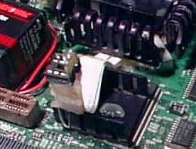
1. First remove the resistors from the R-142 through R-145 positions of the clock multiplier. Then install two 4 wire ribbon cables to provide clearance to tie in an eight prong low profile connection block.
2. Install the first ribbon so it is positioned away from the 603 chip. Solder the four outside connections first, (farthest from the chip). * These pads are all from a common source, so one wire from any of the four positions can supply all the outside terminals on the block. I used all four wires to be safe.
3. Next soldier the inside ribbon to the pads (closest to the chip). Make sure the ribbon connections do not touch. Unlike the outside ribbon, it is important that these four positions remain independent of each other and everything else. Keep the connections clean so they don't cross or short.
4. After verifying the correct continuity, use low temperature, hot glue or something equivalent to hold it all in place.
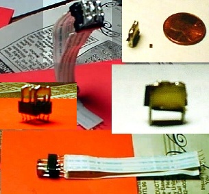
This shows the block with a resistor in the R-145 Position (4.5x)
The resistors are a real "Mac"-Gyver, but they work pretty well.
I installed staples (cut in half) into the block and soldered the resistors across them. Then I used low temperature, hot glue to give them rigidity.
* The old style resistor with a wire out of each end would probably be a time saver and a good substitute.
(3) resistors will be enough to cover all of the possible multiplier settings.
My board requires 1k resistors and the reading across the block without a resistor installed is between 5 and 7K. This is different from what the 64xx at (On Takashi Imai's site) has listed. You should check the resistance on your board and stay consistent with what ever it is.
Note:
* A Cordless Phones is a good source for resistors if you need any. I used an old ( mid 90's) AT&T. The resistors are green and marked "102", just like the 6400 mother board. It wouldn't hurt to have some spares in case you loose or damage
one.
* The two prong crystals from the phone and base
are around 40 MHz and will also work on your board. Not much to gain from
that, but it is nice to know.